
In my quest to get better with electronics and hardware projects, I recently built my own "digital picture frame" project as gifts for my grandparents. I know these things can be bought pretty cheaply, but who knows where your family is uploading their photos to and who has access to the hardware in the picture frames. Plus it seemed like a perfectly scoped project to handle myself over the course of a few weekends and evenings.

Going into this I was pretty confident in my ability to build the software part of this project as it was pretty straightforward. I knew I needed some storage for the photos, a web app to both manage the displays as well as give family members access to manage media, and ideally good mobile support including PWA-like "install" capability so they can put the web app on their home screen without having to build a whole Android/iOS application. But boy did the software aspect not turn out to be as simple as I had pictured.
The part I was less confident in, and where I was looking forward to learning more, was the hardware aspect of this project. I wanted to build a custom picture frame, a classic beginner woodworking project, to house an LCD display. I knew that I would need to design and 3D print a housing for the electronics, and I had planned to keep this low-power enough to run off of a battery.
Goals#
Let's write down a list of what we need to do to achieve our self-hosted digital picture frame project:
- Build software system for managed picture frame
- S3 Bucket for storing photos
- Web application for:
- Managing frame deployments
- Managing media (create, read, edit, delete, etc.)
- "firmware" to query images and run a slideshow on the display
- Build custom picture frame hardware (electronics)
- Design and 3D print housing for electronics
Shopping#
I began by shopping around for electronics components that I would need. I wanted this thing to be low powered enough to run at least 1 day on a decently sized LiPo battery. Initially I considered using a microcontroller like an ESP32 to drive this project. But it turns out graphics libraries to run a GUI aren't all that mature, and 7+ inch displays for microcontrollers also aren't very common.
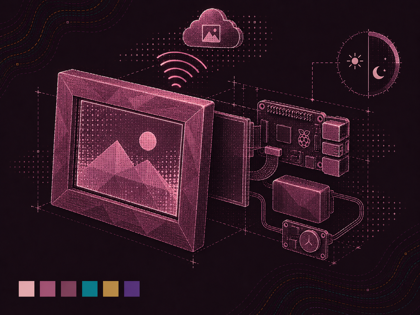
So I pivoted to Raspberry Pis and got a Raspberry Pi Zero 2 W for its low power consumption and small form factor. I also sourced a 1024x600 7-inch HDMI touchscreen display, and a Witty Pi L3V7 RTC board to handle power management and real-time clock functionality to autonomously wake-up / power-off the Pi.
Below is a simplified BOM (bill of materials):
- Raspberry Pi Zero 2 W
- Eventually migrated to a Raspberry Pi 4B (1GB)
- LiPo battery (3.7V, 2000mAh)
- Just happened to be what I had on hand
- 1024x600 HDMI touchscreen display
- Witty Pi RTC and power-management board
- Specifically the "Witty Pi L3V7", which now looks to be deprecated in favor of the "Witty Pi Mini"
- MicroSD card
- 5V power supply appropriate for the Pi, display, and Witty Pi
- Momentary switch to power on/off

Case#
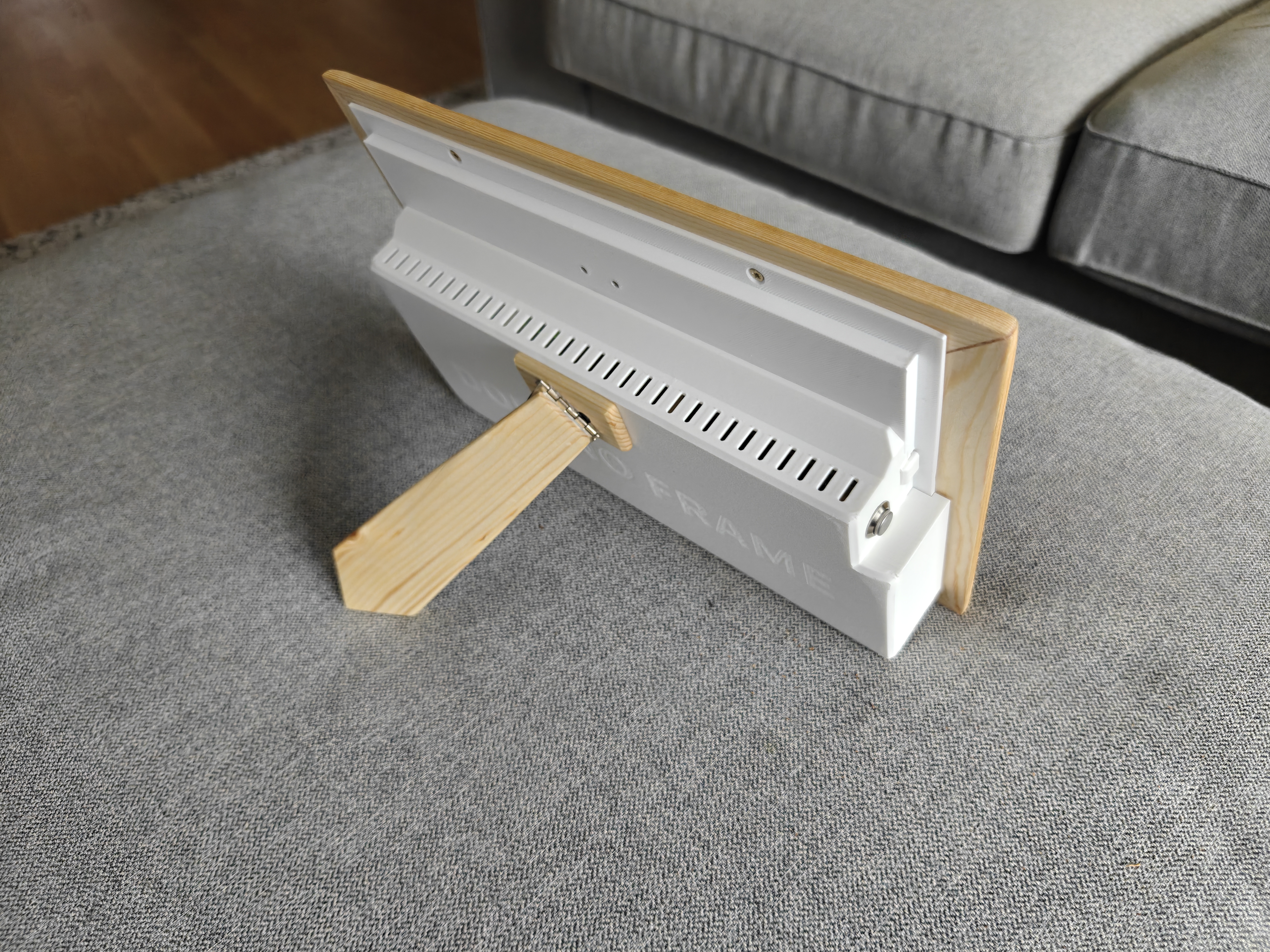
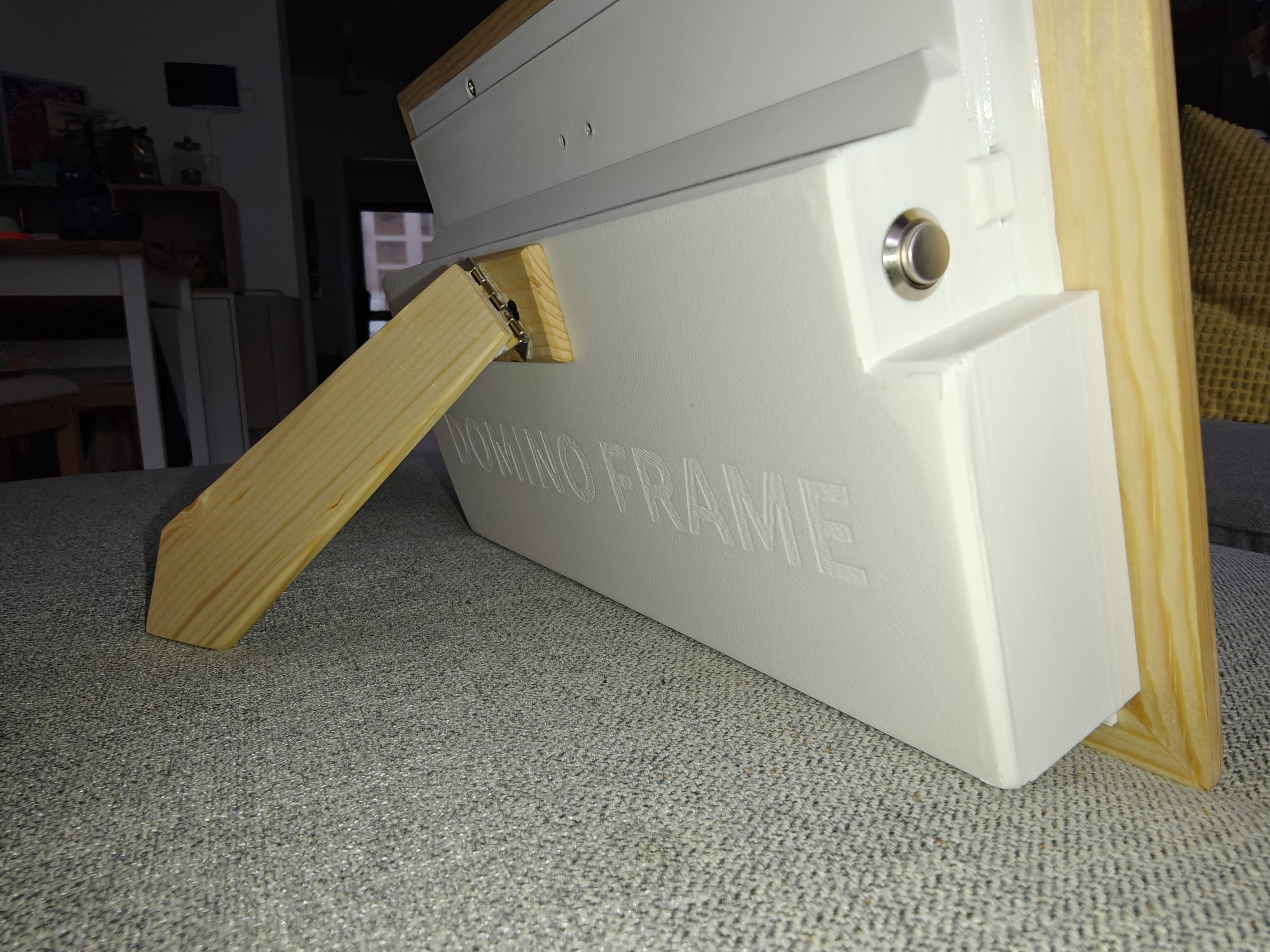
After doing some shopping and waiting for my components to arrive I began to design and model the case. It is designed to be 3D printed and consists of 3 pieces.
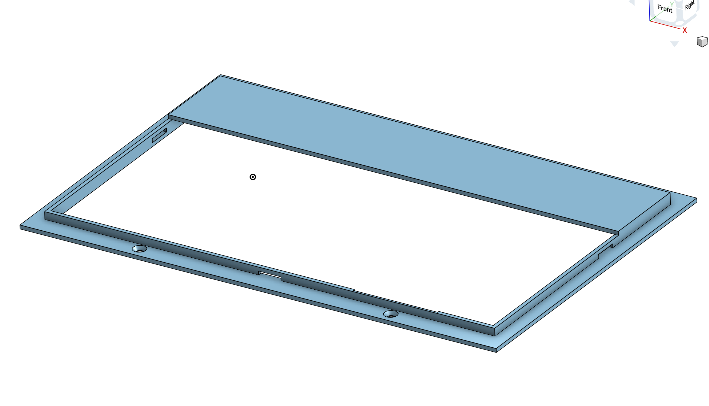
- The initial mounting bracket screws into the wooden frame and serves two purposes. First, it clamps the screen into the inset lip, also known as a rabbet, that I'd cut into the back of the picture frame. Second, it provides mounting options to clip in the rest of the electronics housing.

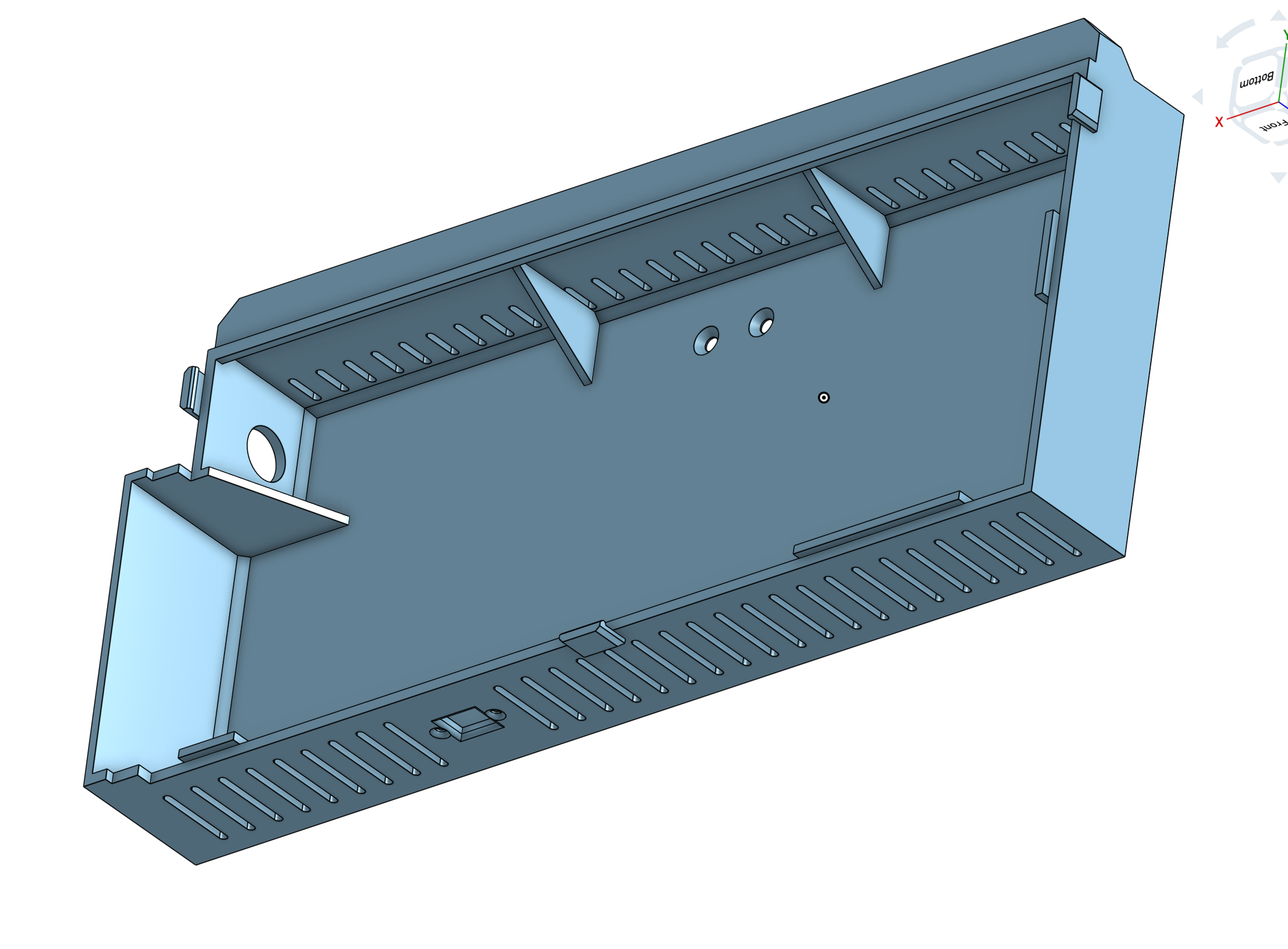
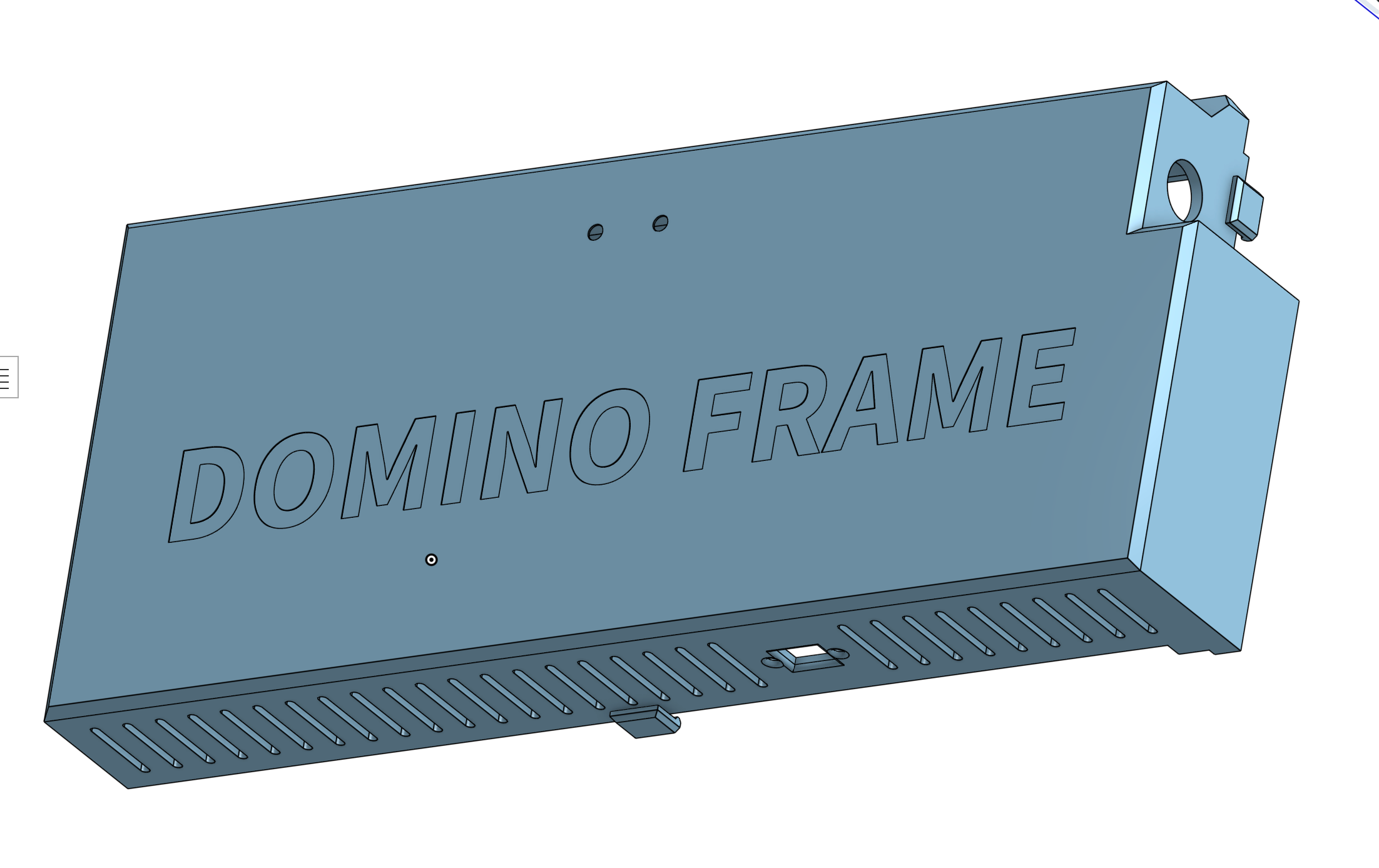
- Next is the primary housing, which contains all of the electronics and gives this a bit of a professional product feel in my opinion. There are ventilation holes as well as a bit of branding inset into the back ("DOMINO FRAME"). In addition, there are cut-outs for a USB-C power cable in the bottom and that aforementioned switch in the left side of the housing.


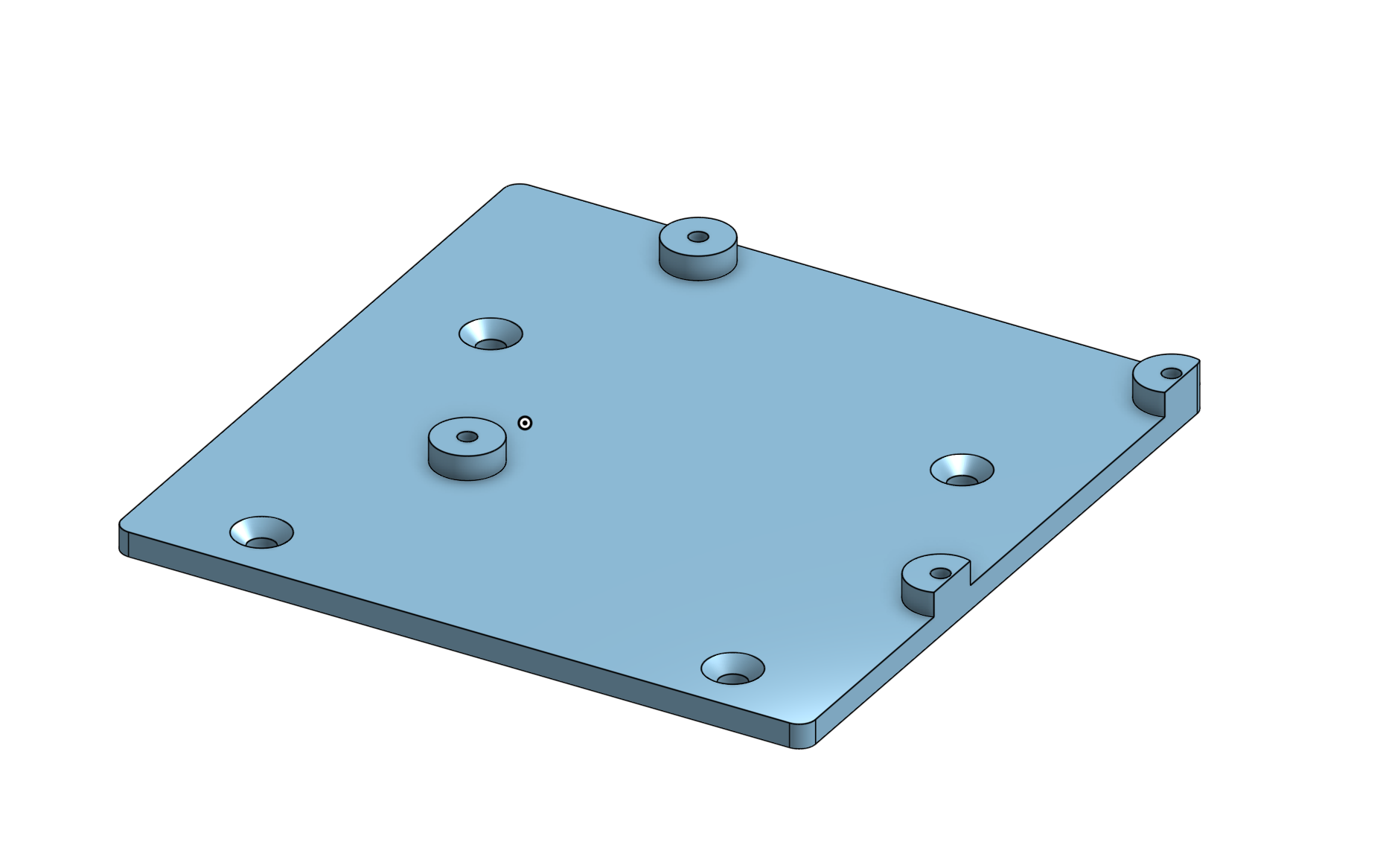
- Finally, a small bracket screws into the factory mounting holes on the backside of the LCD. This provides electrical isolation between the bottom of the Pi and the back of the LCD's aluminum housing, as well as 4 convenient plastic stand-offs to mount the Pi onto. The odd looking sliced-off right edge is due to trying to squeeze this in next to the pre-existing LCD's display board.

Below you can see a dry-fit testing of the assembly of the case parts before final assembly:

The 3D model files can be found at the MakerWorld / Printables pages below.
Electronics#
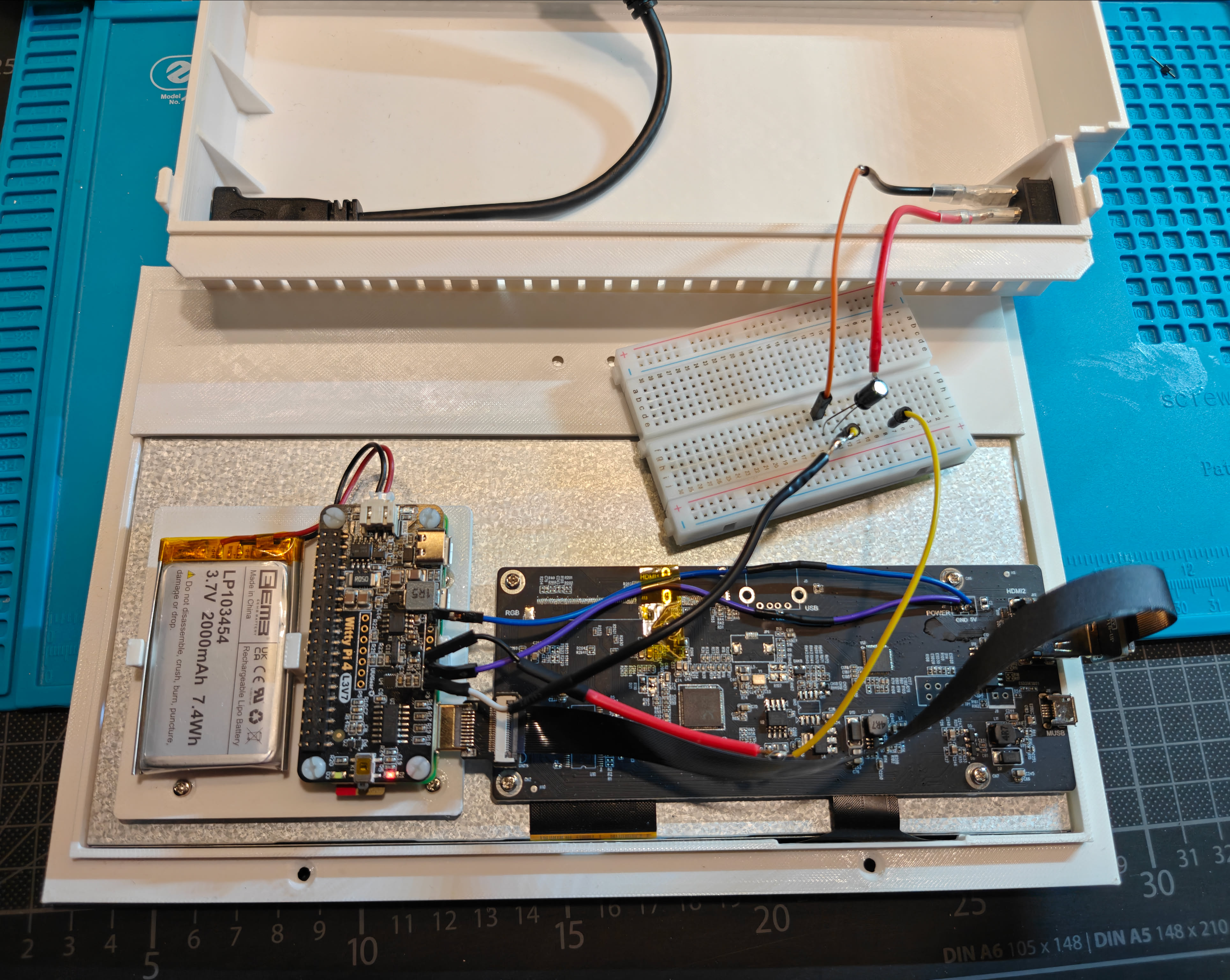
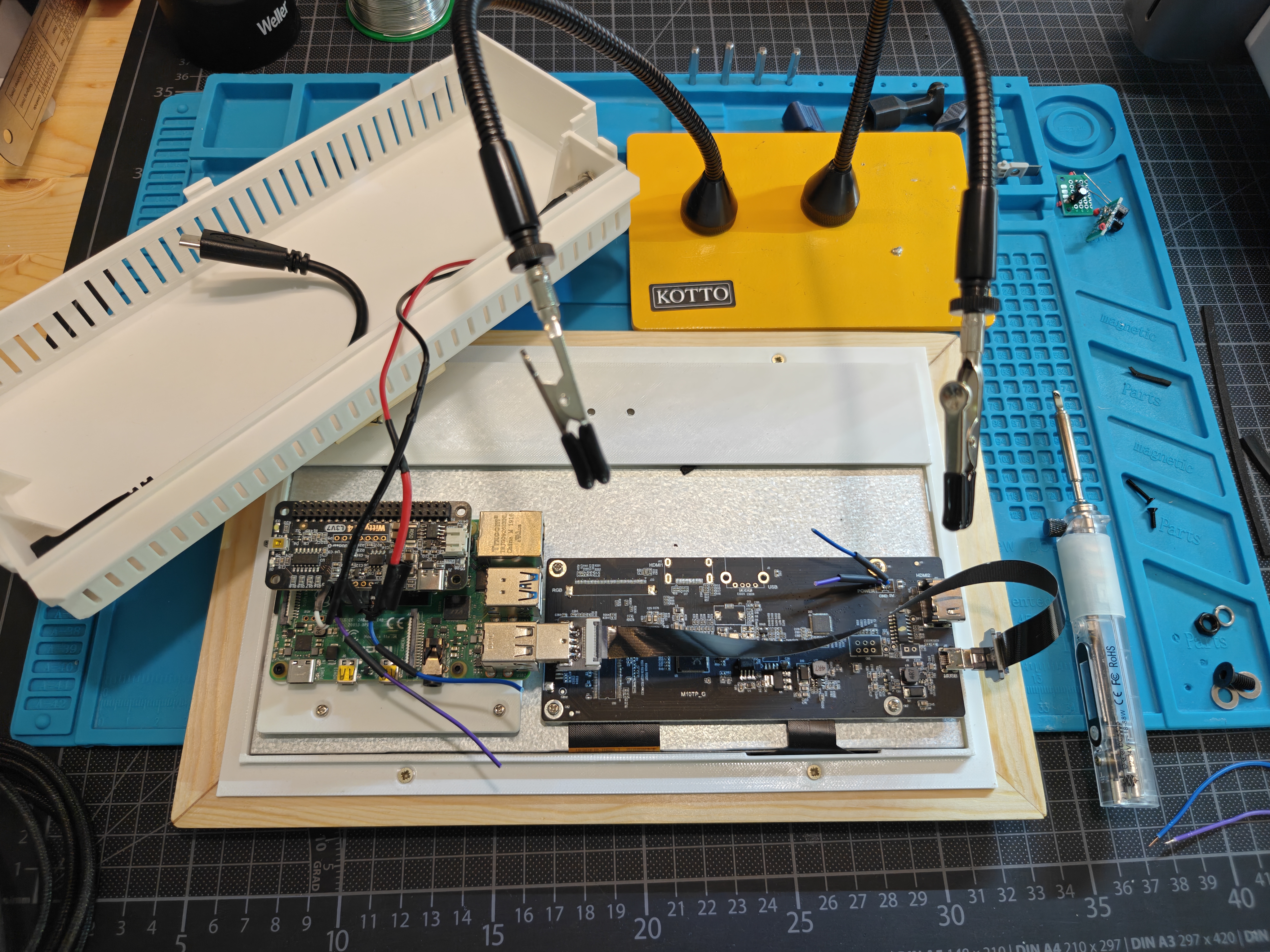
Eagle-eyed readers may have noticed references to two different Raspberry Pis. Unfortunately it turned out that the Raspberry Pi Zero 2W was just not powerful enough. In hindsight this was almost certainly due to my inefficient "firmware" application. All it had to do was query an S3 bucket and run a slideshow on the screen. However, the subtle image animation effects and navigating backward/forward were painfully slow on the Zero 2W. So I switched to an older Raspberry Pi 4B (1GB) that I still had on-hand. This handled the decoding and UI rendering much more smoothly.
Here's a look at how the Raspberry Pi 4B mounting and electronics panel turned out.

I've referenced "firmware" in quotes a few times in this post. The reason for that is that my software played the role of a firmware if this were an embedded project. But for simplicity's sake, I opted to just run the standard Raspberry Pi OS and write the auto-started application in Go because it had some lightweight UI libraries available for Linux desktop applications. The Go application itself turned out to be quite straightforward, leveraging the fyne toolkit for the GUI and minio-go for interacting with the S3-compatible storage backend. I'm far from a Go expert, so this was written with significant help from Claude and co.
Power scheduling with Witty Pi#
I wanted the frame to behave like an appliance. It should turn on in the morning, run during the day, then shut itself down at night without depending on the operating system staying awake.
This is where the Witty Pi L3V7 comes in. Its RTC and power controller can be used to schedule startup / shutdown and use a battery to maintain power during brief outages or transitions, ensuring a graceful shutdown sequence before cutting power. This allows the system to save state and close files properly without risking data corruption on the finnicky microSD cards used to run Raspberry Pis.
The current schedule is:
- Power on at 08:00
- Power off at 20:15
pi@domino-frame-8dp4:~ $ cat wittypi/schedule.wpi
# Try to turn on your Raspberry Pi every hour sharp.
# This script doesn't schedule the shutdown, which is supposed to be done externally.
# You can shutdown your Raspberry Pi with your program just after finishing the job.
#
# [Tips]
# Although the ON state is marked as 1 minute, its actual duration may vary.
# The OFF state will end exactly 60 minutes after your RPi gets turned on.

BEGIN 2022-08-01 08:00:00
END   2035-07-31 23:59:59
ON    H12 M15
OFF   H11 M45
That keeps the Pi on for 12 hours and 15 minutes, then off for 11 hours and 45 minutes. This helps reduce overall power usage with the bonus side-effect of calming the nerves of all grandparents who are still chasing us about leaving the lights on.
Unfortunately, after having migrated to the Raspberry Pi 4B, the small LiPo battery I had chosen is not nearly enough to run this for any significant amount of time. I kept it in as it still acts as a short buffer to allow the Pi to properly power off when unplugged.
Software#
Client Software#
The frame application is a small Go program that runs full-screen on the Pi. It pulls photos from a Cloudflare R2 bucket defined via env vars in the systemd service and presents them as a slideshow. Each image gets a slow Ken Burns-style movement, with a small zoom and alternating diagonal drift, so the display does not feel completely static.
The screen is touch-enabled, but I did not want visible controls covering the images. Therefore I added transparent "buttons" that covered the entire left and right halves of the screen overlaying the image and turned them into tap zones for navigating through the slideshow.
The "firmware" is open source and can be found here.
Web Application#
The web application is a simple Next.js application hosted on Vercel. It provides the following functionality:
- Onboarding new frames
- Manage existing frames (rename, reboot, etc.)
- Manage the media library of each frame
My target audience is my family members, who overwhelmingly use this application from their phones. I'm significantly more experienced building and maintaining web applications as opposed to mobile apps, so I designed this web app to be responsive and work well from mobile browsers. I also included a PWA-style manifest.json which allowed it to be "installed" to users' home screens on iOS and Android. I decided to not go full-on progressive web app and skipped a service worker. That way we skip a lot of the typical caching and service worker complexities, but retain the PWA-style installability.
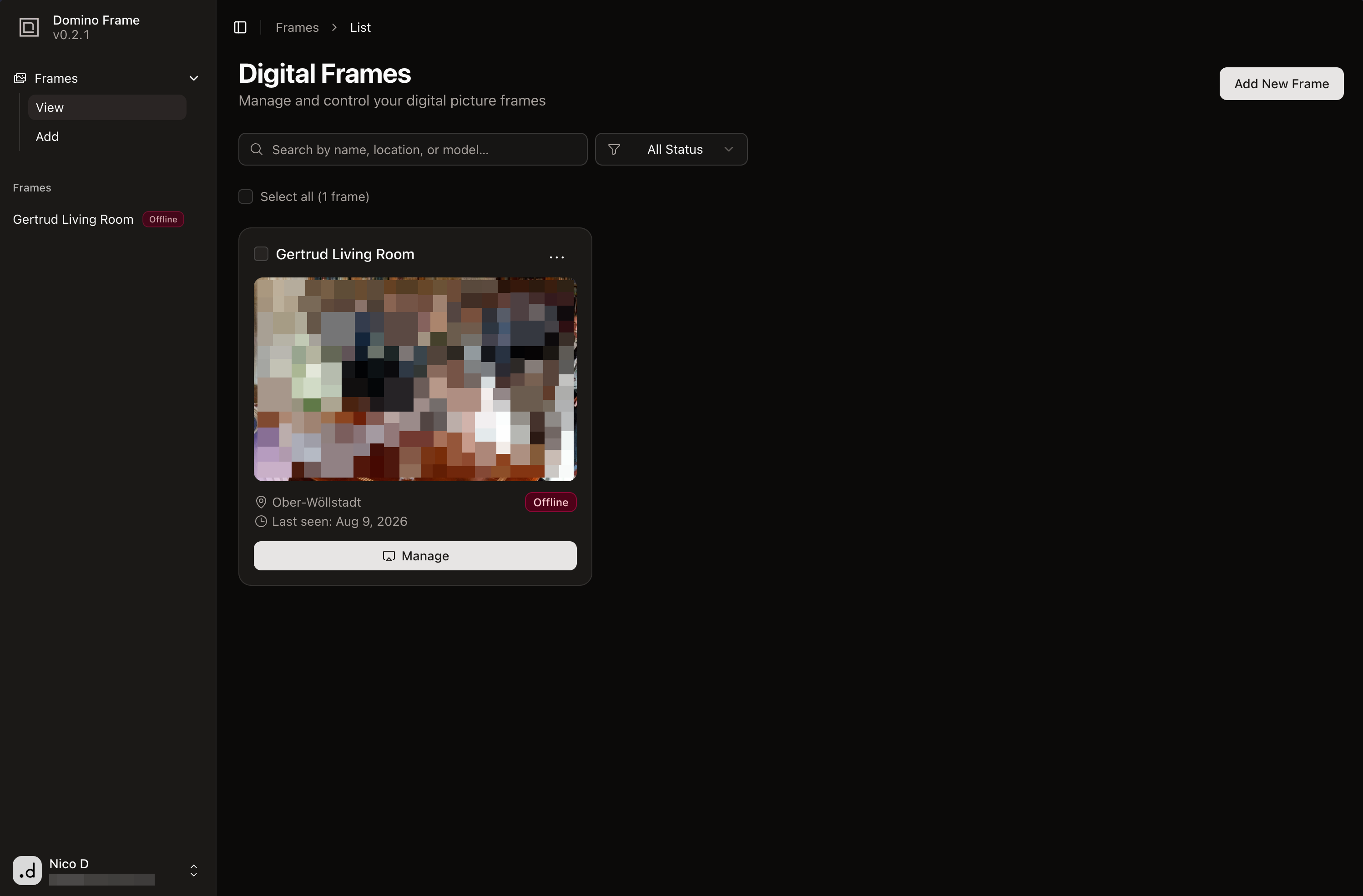

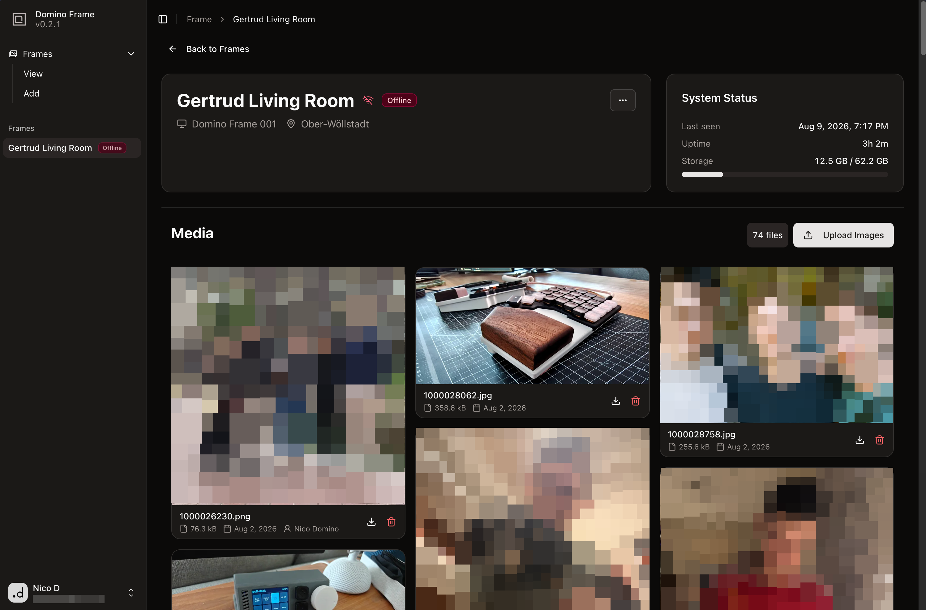

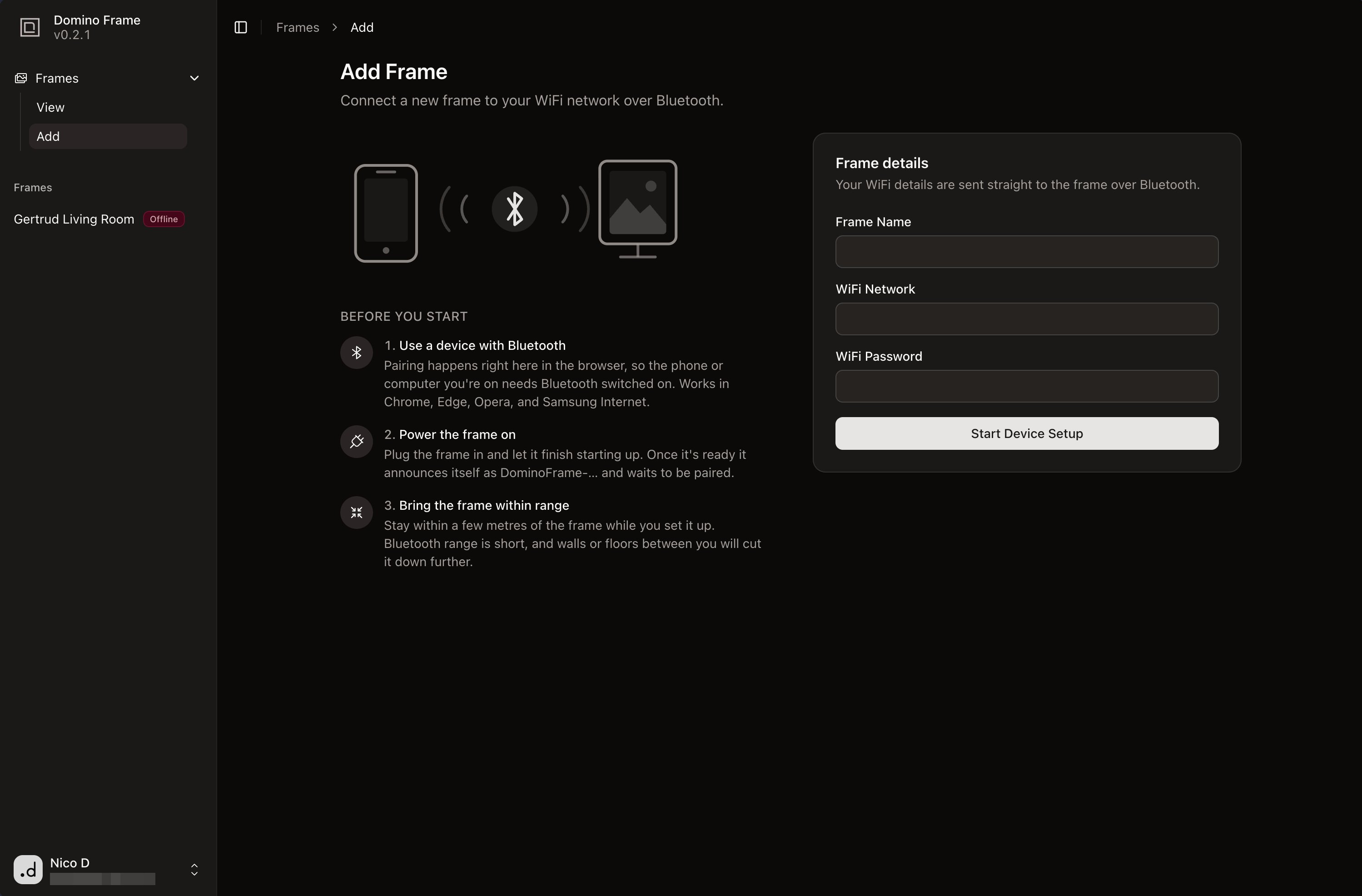
All of the CRUD functionality around managing Frames and their media is very straightforward and was easy enough to implement. However, I really wanted a grade-A on-boarding experience for new frames (even though realistically there will only ever be 2-3 of these devices out in the wild max and I will be the one setting them up haha).
Many devices in the Home Assistant ecosystem, including ESPHome and Matter devices, use something called Improv to manage onboarding a new device onto WiFi. The target IoT device exposes a BLE GATT endpoint, and supported browsers can send setup data, such as WiFi credentials, directly to it. This is generally a great experience and I wanted to emulate it. Domino Frame does not implement Improv itself. I used a custom BLE GATT service with the same general idea.
When the Go application starts, it advertises the custom service as DominoFrame-<frame ID>. In a supported browser, the web app filters bluetooth devices by the "DominoFrame-" prefix. Once a new frame device is selected, the browser connects to the service and first registers the frame via and API endpoint to generatean API key for the frame.
The browser then writes WiFi credentials and frame configuration to separate BLE characteristics. The configuration includes the frame name, image host, API endpoint, and API key. Finally, it sends a complete_setup command. The frame connects to the requested WiFi network with NetworkManager, verifies that connection, and saves the configuration to a local config.json file. There is also a test_wifi command in the setup sequence, though it currently only pings 1.1.1.1; the actual WiFi connection happens during complete_setup.
I knew Web Bluetooth made this local BLE onboarding experience possible from the browser, but getting it to fully work was the most complicated and head-scratching part of the whole project. First of all, support for this API is spotty among browsers, especially the BLE GATT part. Second, the common Linux Bluetooth stack package is super out of date on the Raspberry Pi OS repo, so I had to manually compile the latest version of BlueZ a few times. Maybe I should have just skipped this by creating the DB entry manually for every new frame and writing out its config file by hand whenever a new set of family members gets one of these 😂

You can find the Next.js web application on GitHub here.
Summary#
I'm very happy with where we landed. It achieved all of the goals we defined at the beginning. The frame looks like an actual picture frame from the front, while the back has just enough custom hardware to make the project feel like a small product instead of a Pi taped to a display.
The project ended up being just the right amount of challenging and rewarding. The first Pi was underpowered, Bluetooth onboarding was much more work than it had any right to be, and fitting the electronics cleanly into the frame took several rounds of CAD and test prints. None of that was particularly surprising in hindsight, but it was a lot of fun to work through.
There are still things I would change if I made another batch, of course, but my v1 of this frame is now out in the world showing family photos, turning itself on in the morning, and going to sleep at night.
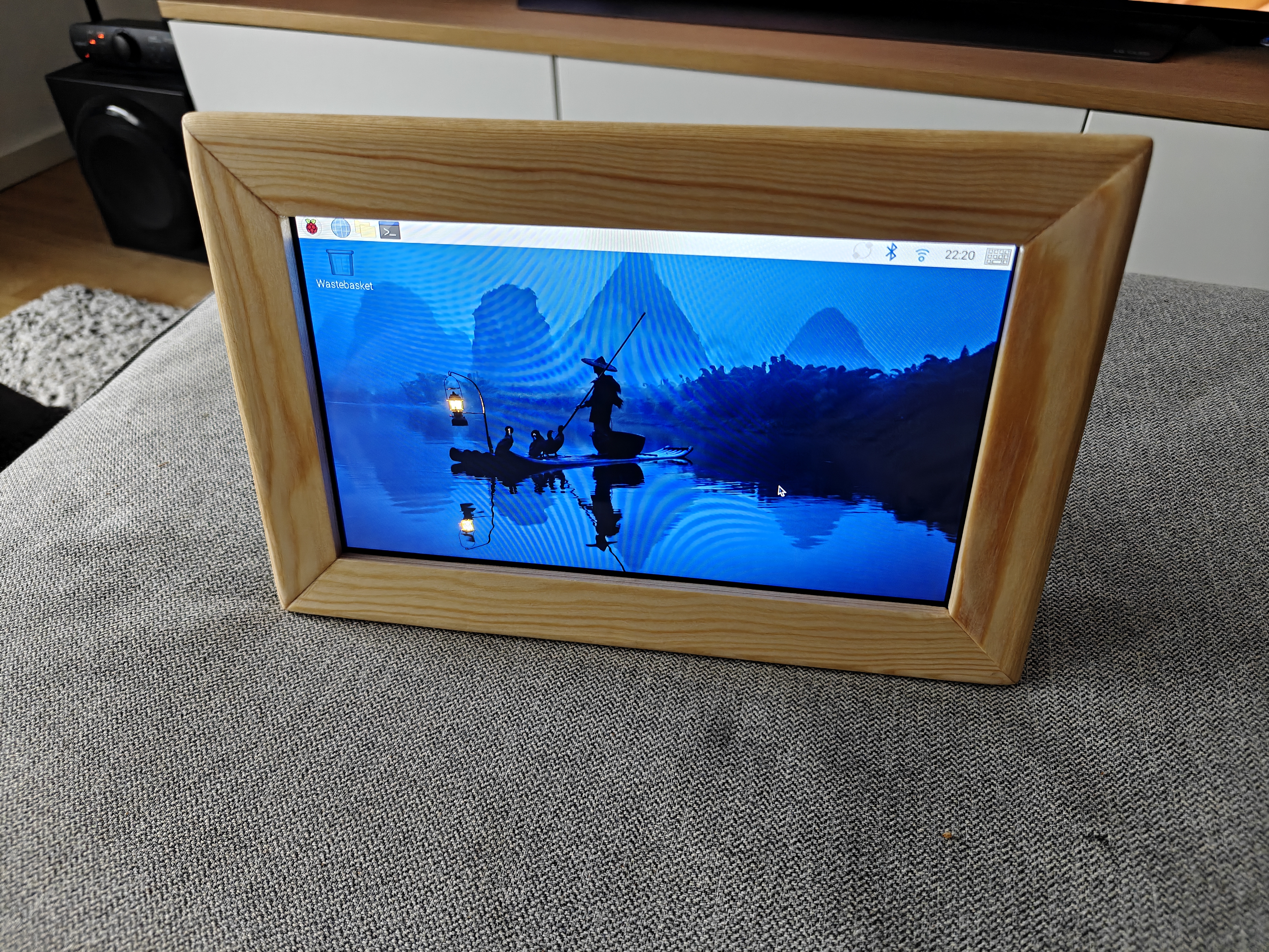
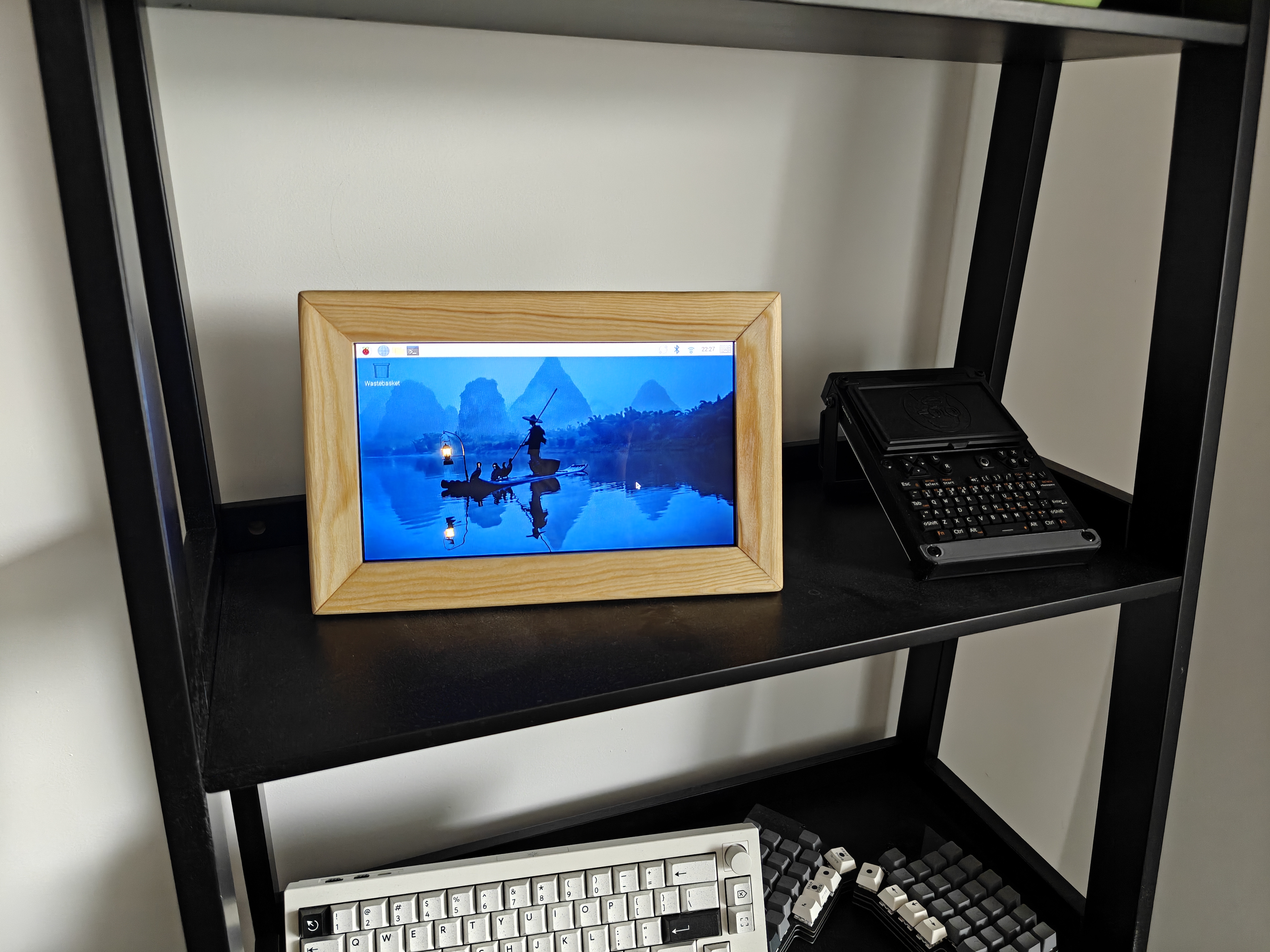
Here are a few more photos of the finished frame.